Of course You need to assign what You want to read first, thought You will do the job
")
.
AI1A will not be configured at the I/O-Assignment. Here You will see where it is assigned to. So it is Read-Only. It auto-assigns if You turn Referency over AI1 or thermal protection over AI1 etc.
But however, the ATV630 is not able to use a pt100 on AI1. Only voltage+current as I can remind.
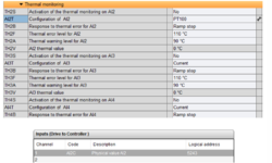
You will need to use AI2 for example, wire it to AI2-COM and change AI2T to PT100. Then check for AI2C for physical and AI2R for standardized values. For completely unfiltered values You could read SAI2.
Hello and thank you again!
According to what has been precedent:
1) it is understandable now that AI1 only reads voltage or current as set in the drive configuration. For both cases, the resultant values (whether in mA or V) can be seen from the VFD webserver. Can we observe voltage/current in TIA (specifically in the DB which contains the variable of MB_DATA_PTR)? Since AI1 is already set to Voltage:

and can be directly read from the webserver, why the resultant physical output voltage value cannot be seen in TIA, although AI1C is preset in the Drive I/O Profile?

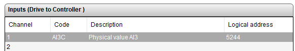
2) Concerning AI2: it is clear now that it can be set to be connected with a PT100 (2-wires), where the first wire of it goes to AI2, and the other to COM. Progressively, AI2T is set to PT100, and AI2C is defined in the Drive I/O Profile:

Result: I kept seeing the value "
10000" on the INT variable assigned to MB_DATA_PTR (as a note, MB_MODE = 103 , MB_DATA_ADDR = 0 , and MB_DATA_LEN = 1 were set at that stage), regardless of the "real temperature value". I also have tried to change the TH2S (Activation if the thermal monitoring on AI2) to Yes but automatically received an Error:
T2CF (Thermal sensor error on AI2).
On the same side, I tried to seek different registers than the AI2C, to get any meaningful readings from AI2, such as
SAI2, but still I only received a stubborn value of "10000" regardless of the actual temperature.
3) As another feedback from the VFD, It would also be beneficial if I can read the states of its embedded relays. As a first trial, I have set
R1 (R1 assignment) to "Device in ready or running state":

And also defined it in the Drive I/O:

When the drive is ON and ready, I have set MB_MODE = 103 , MB_DATA_ADDR 0 = , MB_DATA_LEN = 1 and MB_DATA_PTR is assigned to a BOOL bit, instead of seeing TRUE (as supposedly) the entire MB_Client FB went into an error (16#8383).
4) how possible it is to write a command (e.g., frequency write as initially in this post), read a PT100, and read a BOOL bit from the VFD at the same time?


 .
.